
 English
 Español
Submit feedback

What materials are used to build a car bumper mold
How do they affect mold life?
Car bumper molds must withstand high injection pressures (80–150 MPa), abrasive glass-filled polymers (10–30% glass fiber), and thermal cycling (mold temperature cycles between 20°C and 80°C per shot). The choice of mold steel determines the number of shots before refurbishment.
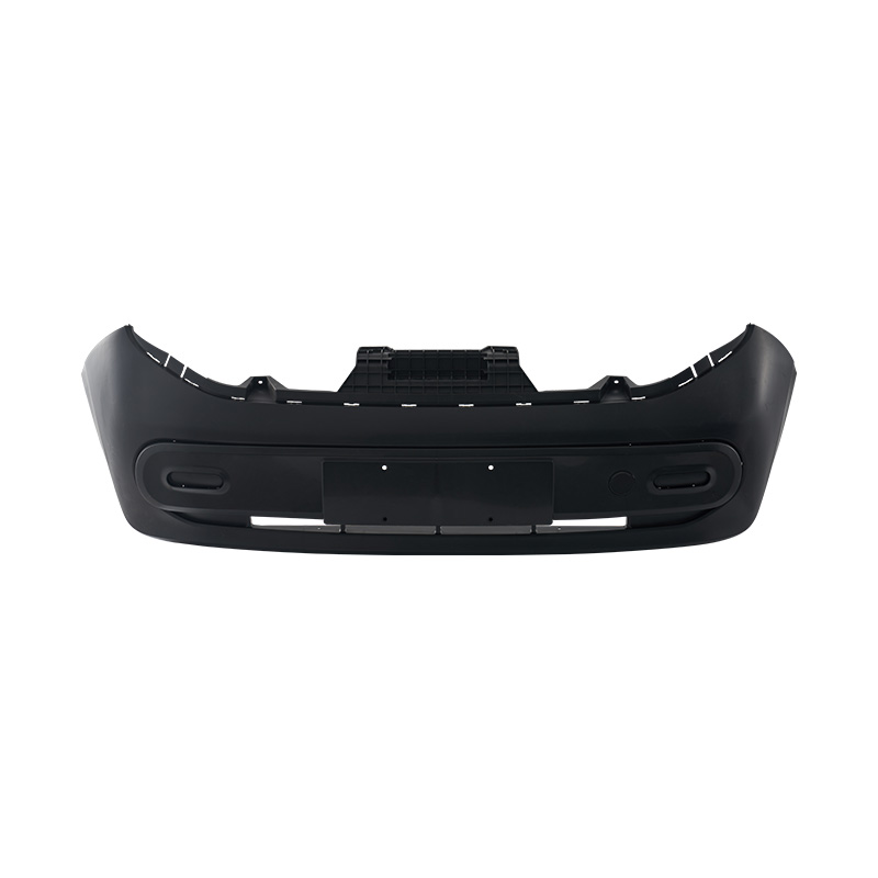
Mold steel grades and their applications:
- P20 (pre-hardened tool steel, 28–32 HRC): Used for prototype molds and low-volume production (under 100,000 shots). P20 is easy to machine but wears quickly when molding glass-filled PP. After 50,000 shots with 20% glass-filled material, the gate area erodes by 0.1–0.2 mm, causing flash. P20 molds cost 30–40% less than hardened steel molds but last only 6–12 months in production.
- H13 (hardened to 48–52 HRC): The most common steel for production bumper molds (300,000–500,000 shots). H13 resists heat checking (fine surface cracks from thermal cycling). At 500,000 shots, an H13 mold may show 0.05–0.10 mm deep heat checks in the gate area. These can be polished out once or twice. Total life: 1–1.5 million shots before major refurbishment.
- 420 stainless steel (hardened to 50–54 HRC): Used for molds running corrosive polymers or in humid environments. Provides similar strength to H13 but resists rust from cooling water leaks. More expensive (20–30% higher than H13). Life: 1–2 million shots.
- Beryllium copper (for core pins and thin sections): Beryllium copper (Alloy 25, 36–42 HRC) has very high thermal conductivity (5–8 times that of steel). It is used for localized cooling where steel would take too long. For example, the sharp corners around fog light bezels cool slowly in steel (15–20 seconds), creating sink marks. With beryllium copper inserts, cooling time drops to 5–8 seconds, eliminating sink marks. However, beryllium copper is expensive (3–5× steel) and machining requires special ventilation (beryllium dust is toxic).
Mold life expectations:
Low-volume (<50,000 parts/year): P20 mold, refurbish after 2–3 years.
Medium-volume (50,000–200,000 parts/year): H13 mold, refurbish every 3–4 years.
High-volume (200,000–1,000,000+ parts/year): H13 or 420 stainless with chrome-plated cavity surfaces (10–20 µm hard chrome). Chrome plating reduces wear and improves part release. After 2 million shots, the mold may need new chrome plating and gate replacement.
How does the cooling system design affect bumper mold cycle time and part quality?
Cooling accounts for 60–75% of the total cycle time in bumper molding. A well-designed cooling system reduces cycle time from 90 seconds to 60 seconds—a 33% reduction in production time.
- Conformal cooling channels: Traditional straight-drilled cooling channels (12–16 mm diameter) leave large temperature gradients. The hot spots (near the gate, at deep draws, around ribs) may be 20–30°C hotter than the cooled areas. Conformal cooling uses 3D-printed inserts (DMLS) with channels that follow the bumper contour. A conformal-cooled bumper mold reduces temperature variation to 5–10°C. Cycle time reduces by 15–30%. The mold insert costs 2–3× more than a standard insert but pays back in 6–12 months through faster cycles and lower reject rates.
- Bubbler and baffle cooling for deep recesses: The bumper has deep draws (around fog light pockets, tow hook covers) where standard channel cannot reach. Bubblers (small tubes inserted into drilled holes that direct water to the bottom of the hole and back) or baffles (metal plates that split the water path) provide cooling. Without bubbler cooling, the deep draw area takes 30–50% longer to cool. In a 60-second cycle, that area may still be 70–80°C when the mold opens, causing the part to warp.
- Water flow rate and Reynolds number: For turbulent flow (efficient heat transfer), the water Reynolds number must exceed 4,000. For a 12 mm diameter channel, turbulent flow requires flow rate > 12 L/min. A large bumper mold may have 10–20 cooling circuits, each requiring 12–15 L/min, for a total of 180–300 L/min of water. A cooling tower with a chiller of 80–150 kW capacity is typical. If flow rates are too low, laminar flow occurs, and the cooling efficiency drops by 40–60%, doubling the cooling time.
How do you prevent warp and dimensional distortion in a large bumper mold?
A bumper cover is a thin, large part (wall thickness typically 2.5–4.0 mm, overall size up to 2 m × 0.6 m). Warp is the most common defect because of uneven shrinkage.
Causes of warp:
Uneven cooling (as discussed above). The side that cools faster shrinks less than the side that cools slower. A temperature difference of 20°C across the mold creates a warp of 3–5 mm over a 1.5 m length.
Improper gate location. A single gate at one end of the bumper (old technology) produces a flow pattern that freezes in high orientation in the flow direction. The material shrinks more in the flow direction than across it, causing the entire bumper to bow (curl). Modern molds use 2–4 valve gates (hot runner system) placed at strategic locations along the bumper length. The gates open sequentially to balance flow. A 4-gate system reduces warp from 5–8 mm to 2–3 mm.
Incomplete packing. When the mold cavity is full, the injection screw applies holding pressure (packing) to push in more material as it shrinks. If the packing pressure is too low or the gate freezes too early, the bumper loses pressure and shrinks unevenly. A pressure transducer in the cavity monitors the pressure at the end of fill. Good packing maintains 30–50 MPa for 2–4 seconds after fill. Poor packing shows decay to zero within 1 second, and the warp increases by 50–100%.
Corrective actions for warp:
Adjust the mold temperature profile. Increase temperature on the concave side (which shrinks less) by 5–10°C, or decrease temperature on the convex side. A 10°C change changes shrinkage by about 0.1–0.2%, which translates to 2–4 mm over 2 meters.
Adjust the packing profile. A "stepped" packing pressure (high for 2 seconds, then lower for 3 seconds, then zero) can balance shrinkage. The optimal profile is found by trial (design of experiments, DOE).
Use a "shrinkage compensator" in the CAD model. The mold cavity is cut slightly larger than the desired part dimensions to compensate for shrinkage. For PP with 10% glass fiber, shrinkage is 0.5–1.0%. For a 2 m long bumper, the mold cavity must be 2,000 × 1.005 = 2,010 mm (10 mm longer). A mold made without compensation will produce a bumper that is 10 mm too short after cooling.



The company focuses on the field of special equipment manufacturing, and its core business revolves around the design, manufacturing and related technical services of injection molds.
© Taizhou Lingfei Mould & Plastic Technology Co., Ltd.
OEM Injection Mold Factory
